


Abstract
Machine tool monitoring in harsh conditions presents unique challenges. This white paper outlines the development and implementation of vision systems to measure part dimensions under extreme conditions, such as oil contamination, mist, vibrations, and thermal variations. Two key systems are discussed: one for external dimension measurement using shadow imaging and another for oil thickness measurement based on the CSEM Spacecoder. This paper also delves into the development of oleophobic optical windows to protect vision systems and the challenges faced in the Tornos machine environment. It concludes with a proposed measurement cycle and future steps in the project.
Introduction
Machine tool monitoring and control in real time is a critical requirement in manufacturing. The ability to measure and control part dimensions is essential for ensuring product quality. However, this task becomes significantly more challenging in harsh conditions characterized by factors such as oil contamination, mist, vibrations, and thermal drift. In this white paper, we focus on the development of vision systems for measuring part dimensions in such conditions and their integration into the machine tool monitoring process.
Vision Systems for Harsh Conditions
- External Dimension Measurement
- Shadow Imaging Technique
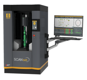
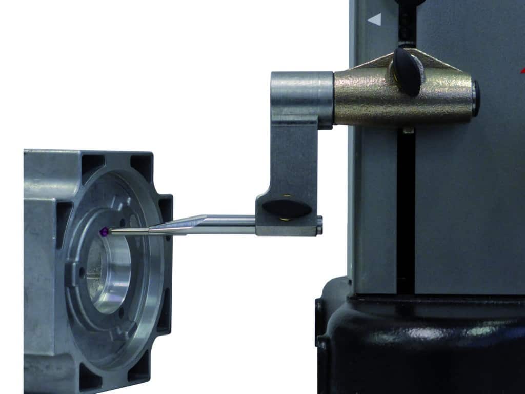
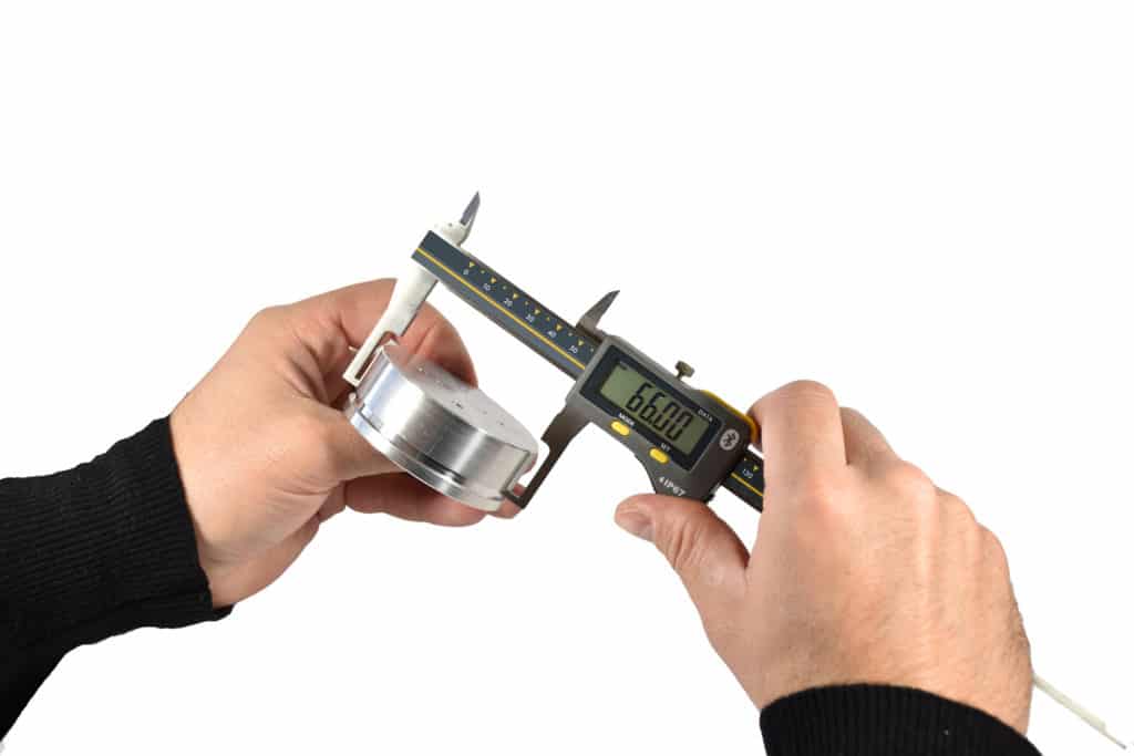
The primary system designed for measuring external part dimensions utilizes the Shadow Imaging Technique, a method inspired by Sylvac optical machines. This approach captures the silhouette of the part’s external features and dimensions, enabling accurate measurements. The heart of this system is a 2D shadow imaging device, a significant advancement from the original Sylvac linear Scan. Here are the key components and features of this system:
2D Shadow Imaging Device
This innovative device represents an upgrade from Sylvac’s linear Scan to a 2D Scan capable of frame scanning, offering a broader range of measurement possibilities. Notably, it leverages AI technology to introduce new features, such as advanced contouring and filtering, ensuring more precise and reliable measurements.
Image Acquisition
The 2D shadow imaging device captures images in two distinct modes, each serving a specific purpose:
- Half Degenerate 2D: This mode is employed during the calibration process with a dummy part, ensuring the system’s accuracy and consistency.
- Fully Degenerate 2D: In this mode, the device essentially captures an almost 1D image of the part, which is subsequently analyzed to extract relevant measurement data.
Image Contouring
To enhance measurement accuracy and consistency, image contouring is performed dynamically through AI-driven processes. This dynamic contouring ensures that the system adapts to variations in the part’s features and dimensions. The contouring process is achieved through a combination of existing techniques developed by Sylvac, such as dark and white contrast analysis with fixed thresholds, and new methods introduced by CSEM and dynamic thresholding.
Filtering
Filtering is a crucial step in the measurement process, aimed at removing unwanted artifacts, such as chips and burrs, that might affect the accuracy of measurements. The system employs two main filtering techniques:
- Comparative Filtering: This method utilizes AI to compare the captured image with a reference image, identifying and filtering out any anomalies.
- Statistical Filtering (Gaussian): Statistical filtering techniques are used to analyze and filter data based on statistical parameters, ensuring that only the most reliable datapoints are retained.
Calibration
The shadow imaging device is finely calibrated to ensure the highest level of accuracy. Calibration involves the optimization of both intrinsic and extrinsic parameters. The machine learns from a multitude of individual data points, minimizing errors at each step to collectively minimize the overall error. The result is an internally optimized system that consistently delivers precise measurements.
This system is a critical component of the overall vision system designed to operate in harsh conditions, providing reliable external dimension measurements even in challenging manufacturing environments.
However, to achieve accurate measurements in harsh environment, specific pre-processing steps have been tested and proven to be essential:
Spinning: The part is rotated at a high speed (4 krpm) to distribute oil evenly and facilitate measurement.
Air Blowing: Air pressure at 6 bar is applied to remove excess oil and maintain surface integrity.
- High-Speed Spinning and Air Blowing
The amalgamation of high-speed spinning and air blowing has emerged as a highly effective method for disseminating oil on the part’s surface. This technique not only facilitates the distribution of oil but also aids in surface geometry recovery, subsequently resulting in a substantial enhancement in measurement accuracy, particularly along the edges of the part. The following results serve as a testament to the efficacy of this approach, clearly illustrating the significant improvement in measurement accuracy achieved through air blowing and spinning.
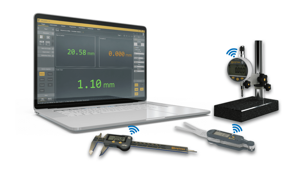
Raw results from this system have showcased remarkable accuracy, with measurements achieving an impressive range of 0.2 µm to 7 µm, even in the most challenging conditions, all of this without the need for calibration. It is noteworthy that the precision of these measurements is closely intertwined with the surface roughness of the part, whereby smoother surfaces yield measurements of unparalleled precision.
It’s important to highlight that both spinning and air blowing, integral systems already integrated into lathe machines, play pivotal roles in this process. They are not only seamlessly integrated but also enhance the accuracy of the measurements.
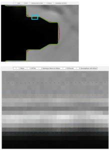
Diameter 6mm, horizontal edge, Ra0.8: <3.5um. In blue the reference measurement whilst in green the measurement after airblowing and spinning
- Oil Thickness Measurement
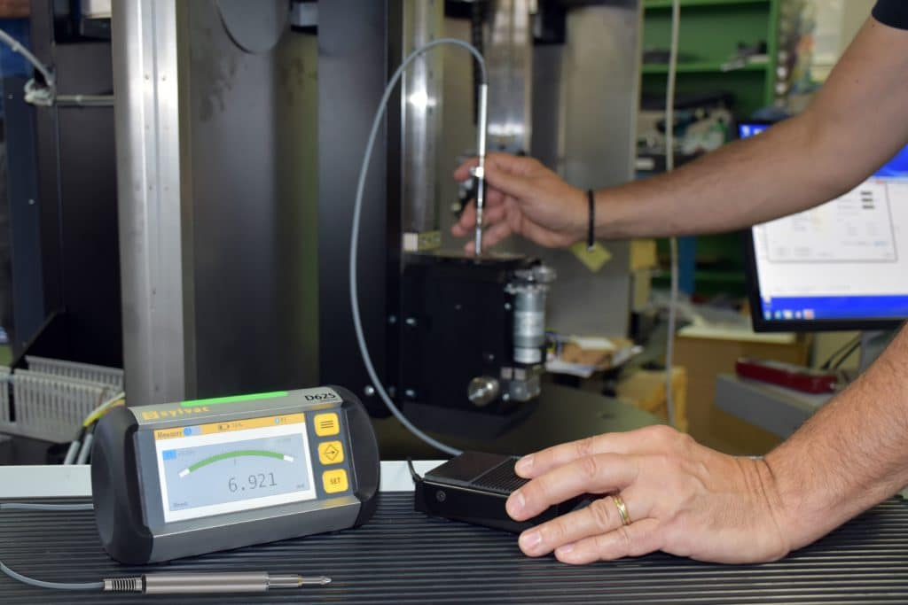
The second system is designed for oil thickness measurement using the CSEM Spacecoder. The key feature of this system is its ability to measure phase shifts in the signal, which are then utilized for triangulation. The accuracy of this measurement is closely tied to the system’s repeatability, which is assessed by computing the phase shift over time within a Region of Interest (ROI).
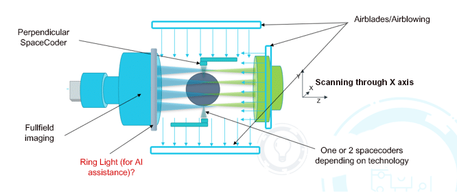
2.1 High Precision Spacecoder Setup
The Spacecoder setup demonstrates high precision, with the ability to measure the shadow of a mask with a precision of 10 nm. This measurement was conducted on a workpiece provided by Sylvac, at a distance of 75 mm, using a framerate of 100 Hz and a 10 ms integration time.
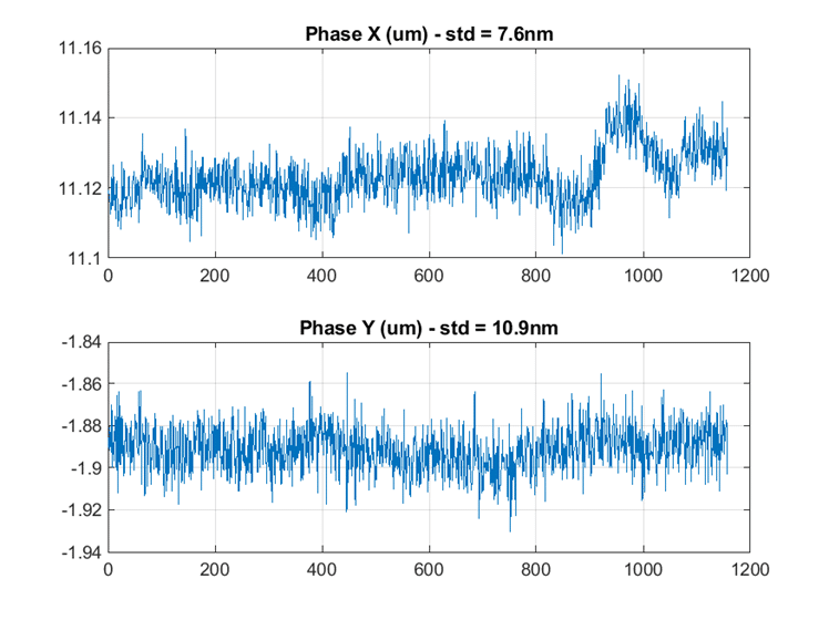
The shadow of the mask, projected on the camera sensor, is measured with a precision of 10 nm. The X axis is time and the Y axis is phase.
2.2 Distance Measurement from Phase Shift
The accuracy of distance measurement from the phase shift is assessed by moving the Device Under Test (DUT) in fixed steps and computing the 3D position of the source through triangulation of the phases from two ROIs. This method achieves sub-micron accuracy in measurements.
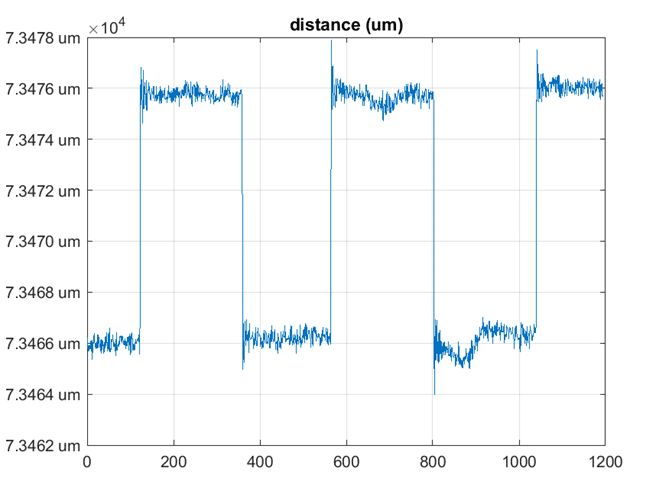
Distance measurement from the phase shift.
Oleophobic Optical Windows
The project also addresses the development of oleophobic optical windows as a means of protecting vision systems in harsh conditions. Two approaches are explored:
- Passive Solution
Oleophobic coatings are applied to glass substrates. The non-fluorinated formulation is favored due to its ability to reduce oil stains after contamination. Parameters such as withdrawing speed and formulation viscosity are crucial in controlling the thickness of the deposited coating. This passive solution is vital for keeping optical windows clean and functional in the presence of oil.
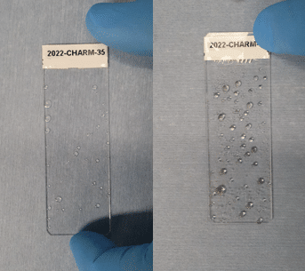
Glass substrates treated with non-fluorinated coating (left) and with fluorinated coating (right)
- Active Solution
An active solution is designed to complement the passive approach. It involves creating a lateral or radial flow to remove oil droplets from the optical window. The system is continually tested in real conditions, and it has shown promising results in eliminating oil contamination. Careful consideration of flow direction and optimization is essential to ensure the efficiency of this method.
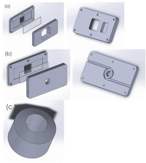
The different stages of the design of the active system: (a) for a lateral flow, (b) for a radial flow, and (c) for an improved radial flow
The proposed measurement cycle involves several steps:
The success of vision systems in harsh conditions relies heavily on a meticulously orchestrated measurement cycle. This cycle is designed to ensure the accuracy and reliability of the measurements while accounting for the challenging environment. Let’s delve into each step, highlighting its significance in the overall process:
- Prepare the part by stopping machining and allowing it to cool.
- Initiate high-speed spinning and activate the air blowing system for oil discrimination.
- Part rotation and air blowing stop, and the first mechanical shutter opens.
- The part enters the measurement device, and internal air blowing keeps mist and chips at bay.
- Metrology begins with degenerate shadow imaging and the Perpendicular Space Coder.
- The second shutter opens when parts approach it.
- After scanning, the part is extracted from the measurement device.
- Both shutters close, and internal air blowing continues for 2 seconds to remove residual mist oil on oleophobic windows.
- Analyze acquired data for part measurability, taking into account temperature and vibration values.
- Allow calibration on a dummy part inside the measuring device during machining operations.
- Repeat the cycle.
Next Steps
Future work should focus on:
- Further testing and optimization of the Sylvac IS (imaging system)and CSEM PSC (perpendicular space coder) with oleophobic windows.
- Assess the behavior of the system with significant temperature changes.
- Rigorous testing of mechanical components and electronics.
- Continuous improvements in vibration measurement, mist and temperature compensation methods.
Conclusion
Vision systems for harsh conditions in machine tool monitoring represent a significant technological advancement. The combination of shadow imaging for external dimension measurement and the Spacecoder for oil thickness measurement offers remarkable accuracy even in challenging environments. Oleophobic optical windows further enhance the reliability of these systems. The proposed measurement cycle provides a structured approach to part inspection in real-time, and ongoing testing and validation are essential for realizing the full potential of these systems in industrial settings.
With ongoing research and development, these vision systems have the potential to revolutionize machine tool monitoring and improve product quality in industrial settings.